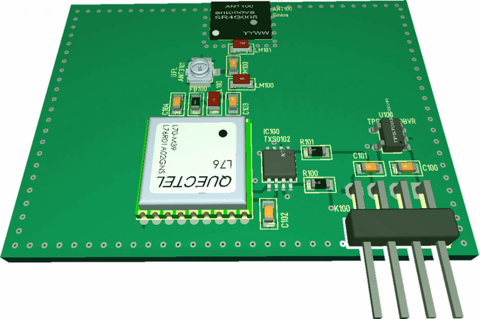
GNSS antenna test PCB made by the akorIoT team
Last week I got a request to support a small GPS tracker. The request is not new to me. It reaches me in several times per year. However, it makes no sense to reinvent the wheel again and again.
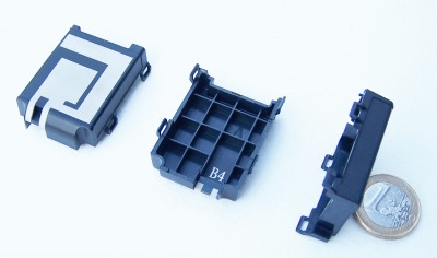
To minimise the effort for your GPS tracking project on NB-IoT, LoRaWAN, SIGFOX or Weightless P the akorIoT team designed a unique GNSS test PCB. The PCB dimensions of 30 mm x 40 mm can be expanded to a customised size to the dimensions of your enclosure.
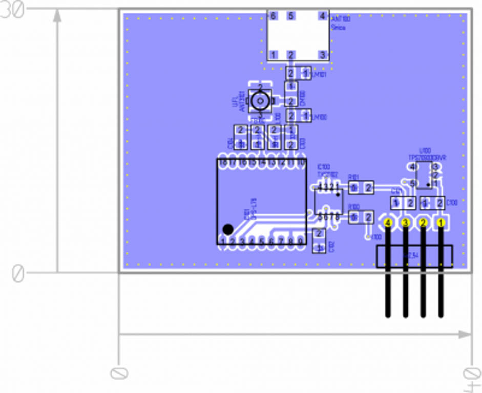
We match The GNSS chip antenna on the new PCB size including your plastic enclosure. The values of the components in the matching circuit will be documented and used on the final PCB. Before the final PCB development starts, there is a step in between. The four pins of the test GNSS test PCB are wired to a USB to UART converter on the test PCB. Based on that you will test the “empty PCB” with a GNSS antenna and GNSS module connected to your laptop.
The NMEA strings will be recorded and later on analysed with free of charge standard software. These NMEA strings contain the position calculated after reading the GNSS satellites, the number of visible satellites and a few more interesting parameters. The NMEA GSA string includes the numbers of the GNSS satellites being used in the current calculation and the DOP. The DOP (dilution of precision) is an indication of the effect of GNSS satellite geometry on the accuracy of the GNSS fix. It is a unitless parameter where smaller is better. For 3D fixes, using four satellites 1.0 is already a perfect value. The number of GNSS satellites you will receive and the better PDOP is direct related to your GNSS antenna design and matching, including the performance of your selected GNSS module. For comparison, you could use a common GNSS mouse and an Android smartphone. The GNSS mouse should give you the best NMEA output to compare with.
Here is an NMEA string: $GPGSA,A,3,05,06,,09,12,,,24,,,,,2.3,1.5,2.2*40
NMEA string in detail:
- GSA Satellite status
- A Auto selection of 2D or 3D fix (M = manual)
- 3 3D fix – values include: 1 = no fix / 2 = 2D fix / 3 = 3D fix
- 05, 06… PRNs of satellites used for fix (space for 12)
- 2.3 PDOP (dilution of precision)
- 1.5 Horizontal dilution of precision (HDOP)
- 2.1 Vertical dilution of precision (VDOP)
- *40 the checksum data, always begins with *
A package including this easy-to-use GNSS test PCB including Eagle files, Gerber files, expansion to a customised size for your enclosure, measurement with a Vector Network analyser inside your enclosure, export of Return Loss values to S1P files before and after matching can all be ordered for €480 from the akorIoT team.
S1P is a common exchange format, you can read the files with free software and print out the Return Loss, Smith Chart and a lot of more.
Hand effect of the GNSS test PCB antenna
The video above shows that the GNSS antenna is stable in the centre frequency and return loss even when a human body is close to the test PCB.
Radiation pattern test in 3 axes
If this is not enough, then the akorIoT team is able to measure the GNSS antenna radiation pattern of the GNSS test PCB for a reasonable cost. We are motivated to help our customers to design world best wireless IoT devices. If you have two minutes left, then watch the video below.
0 Comments