
MegiQ Radiation Measurement Systems
RMS-0440/0460/0640/0660
- Choice of frequency ranges:
- RMS-0440: 370 MHz – 4 GHz: € 14,950.00
- RMS-0460: 370 MHz – 6 GHz: € 16,950.00
- RMS-0640: 600 MHz – 4 Ghz: € 12,950.00
- RMS-0660: 600 MHz – 6 GHz: € 14,950.00
- Measure Antenna Radiation Patterns, TRP, Efficiency, Directivity and more
- Fits in lab or office space
- No need for an anechoic chamber
- Measure 3-axis patterns in under 2 minutes
- Base accuracy ±1 dB
- Repeatability ±0.5 dB
- Complete system includes all hardware and software
- Optional heavy duty table
- 30 day money back guarantee (less any return to stock costs)
- Price includes 1 hours live video training
- Further training available on request to support your project
RMS Overview
The MegiQ Radiation Measurement System (RMS) is a compact test system that performs 3-axis radiation pattern measurement in non-anechoic spaces.
With a frequency range of 370 MHz to 6 GHz covered by the three models, they are well suited for characterization and measurement of Antenna Radiation Patterns, Antenna Gain, ERP, TRP, Field Strength.
Extensive evaluation has shown that – with reasonable setup – the accuracy of the RMS is similar to that of anechoic test labs.
Characterize wireless devices of today, like IOT devices, routers, phones, domotica (home automation) products, electronic gadgets, tablets, laptops, RF-modules etc.
The RMS is used for these measurements:
- Radiated output power patterns of a wireless device
- Harmonic radiation patterns (up to 6 GHz) of wireless devices
- Gain and radiation patterns of standalone antennas, using the generator option
- Gain over frequency of antennas
- Radiation patterns over frequency of antennas
- Beamwidth and max gain of directional antennas, over frequency
While this is usually measured in an anechoic chamber to avoid reflections to affect the measurement, the RMS has a smart antenna design to reduce the sensitivity for reflections. This allows radiation measurements to be made in relatively small lab or office spaces.
The RMS system itself has an accuracy of ± 1dB. In a reasonable space one can expect an extra uncertainty of 1 or 2 dB. The repeatability of measurements is excellent at ±0.5 dB. No user calibration is required.
RMS system diagram
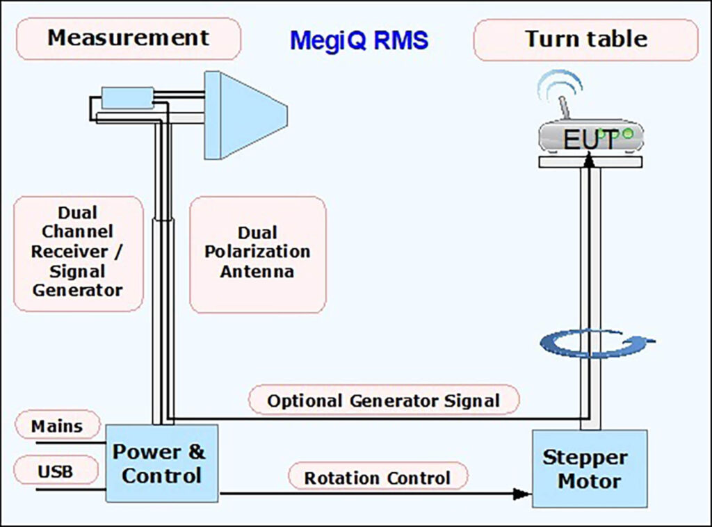
Measurement
- Antenna height 100 cm to 170 cm.
- Dual Polarization Antenna.
- Dual channel measuring receiver.
- Generator output (option).
- Rotation controller unit.
- Power supply.
- USB connection for computer control.
Turn Table
- Height 70 cm and 130 cm.
- Stepper motor drive.
- 30 seconds per rotation.
- Smooth acceleration.
- Table size 28 x 28 cm.
- Max EUT weight: 7.5 kg.
- Heavy Duty table: 100 x 50 cm, 30 kg.
The RMS rotates an object on the turntable and measures the radiation. With a rotation around the X, Y and Z axis the software plots the patterns and calculates statistics including Total Radiated Power (TRP). Each measuring point can contain a sweep of multiple frequencies, so that multiple radiation patterns can be measured in one rotation sequence.
With the Generator option the RMS can also perform an antenna sweep and show the antenna gain over frequency.
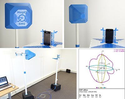
The RMS comes with an object fixture for small devices that allows easy positioning of the EUT in orthogonal positions on the object table. A labeling system helps the user to keep track of the axes.
The RMS system works well in a moderate space. A 4 x 4 x 3 meter room works well above 800 MHz. For smaller spaces or lower frequencies a few strategic absorbers may be required.
Complete measurement system, includes:
- Antenna base with mast
- Measuring antenna
- Measuring receiver
- Turn table with masts
- Turn table platform
- Object fixture
- RMS Software
- Tools for setup and measuring
- Cables
Options:
- RMS-GEN: Internal 3GHz Signal Generator
- RMS-LASER: Internal Laser Pointer
- RMS-HDTT: Heavy Duty Turn Table
- RMS-COAX: 5 meter quality SMA coax
Programming API
With our RMS Application Programming Interface the RMS systems can be expanded with custom features and data processing as well as integration with other systems.
Features
- Turnkey system includes rotation table, measurement antenna and receiver and application software.
- Dual polarization antenna and dual channel receiver.
- Frequency range 370 MHz to 6 GHz (depending on model selected).
- Base accuracy ±1.0 dB (in anechoic environment).
- Repeatability ±0.5 dB.
- Factory calibrated. No user calibration necessary.
- Measuring distance 0.8 to 3 meter (~3 to 10 feet)
- Measures the phase between H and V polization.
- Measures Constant Carrier, PRN9 and packet streams.
- Measures multiple frequencies at the same time.
- Measures 3-axis radiation patterns in minutes.
- Needs only one rotation per axis.
- 3D representation of measurements.
- Measurement quantities:
- Field Strength
- EiRP
- Total Radiated Power
- Antenna Gain
- Antenna Efficiency
- Front to Back ratio
- 3dB / 10db Beam width
- Real-time power and polarization indicator.
- Generator-port option allows closed loop
measurement of an Antenna under test up to 3GHz. - MegiQ VNA can be used as a tracking generator up to 6 GHz.
- System can generate a horizontal or vertical test signal.
- License free software included.
- Session manager for storing measurements and configurations.
- Versatile report output.
- Heavy duty table optional.
- Can be used in normal office space with moderate space requirements.
- No need for an anechoic chamber.
- Compact and portable system.
- Programming API for enhancing functionality.
RMS Software
The software for controlling the RMS and managing the measurement data is provided license free.
The RMS software controls the measurement system and allows easy setup and performing the measurements, organizing the data and create reports. It will guide the user through the 3 rotation axis steps.
For EUT with a constant carrier or packet stream mode the RMS is used in a passive mode to rotate the EUT and record the field strength. For constant carriers, the receiver can measure multiple frequencies for each measurement point so that harmonic patterns (up to 4 or 6 GHz) can be measured simultaneously. The minimum step size is 2 degrees.
For EUT without a transmitter (prototype or standalone antenna) the Generator output can be used to feed a test signal to the EUT. In this mode the RMS can measure rotation patterns (at up to 30 frequencies simulations) or perform a frequency sweep of the antenna gain. The S- parameters of the feed coax can be imported to compensate for the loss and impedance of the cable.
In idle mode the RMS monitors the signal and shows the polarization in real time. It can also transmit a carrier with a calibrated power on the horizontal or vertical antenna.
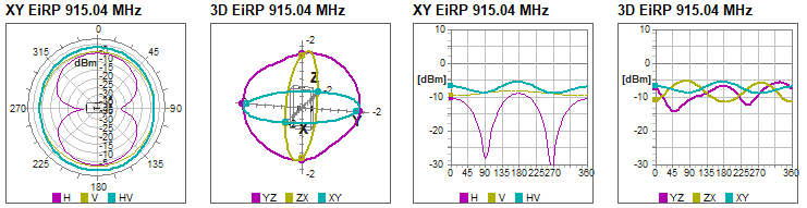
The results can be presented in Antenna Gain (dBi), Radiated Power EiRP (dBm) or Field Strength (dBuV/m). The software calculates statistics such as Min/Max level, Average, Total Radiated Power (TRP), Antenna Efficiency (dBi) and Directivity (dB).
The rotation table can be controlled manually and a rotation offset aides in the rotation of large objects.
With several preset measurements the software is very easy to use for most common measurements like rotations and sweeps.
The graphs can be dragged in any way with any of the graph types for the measurement. Report output follows the layout of the screen. There are several color schemes.
Measurements can be stored in a session manager that keeps the measurements for a session in a single file. All settings including cable correction, screen layout, markers etc are stored along with the measurement in the session.
For measurements that use the generator output or an external generator, the S-parameters (attenuation) of the feed coax can be imported in the software to compensate the measured data.
An Application Programming Interface for VB, C++, C#, Labview, etc is available to allow integration of the RMS in a lab setup or an automated factory testing system.
Measurements
These are some measurements and graphs measured by the RMS system.
Radiation Pattern
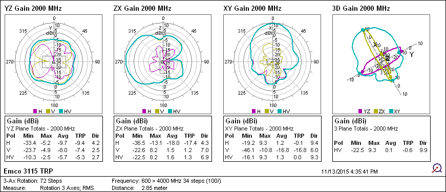
Rotation and Linear patterns
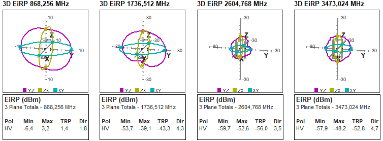
Harmonic radiation patterns
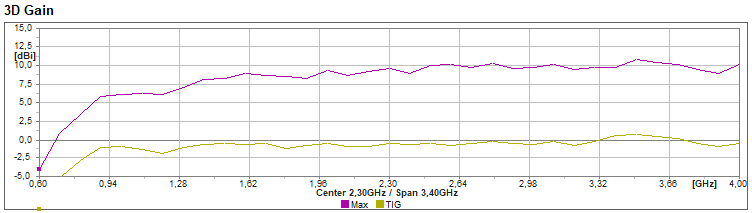
Max Gain and Efficiency (TIG) over frequency
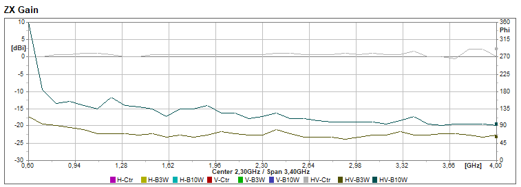
Front to Back Ratio over frequency
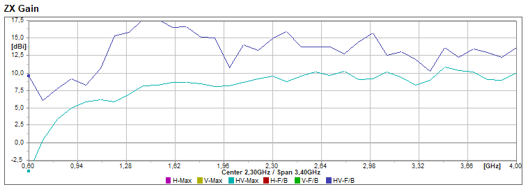
Beam Width over frequency
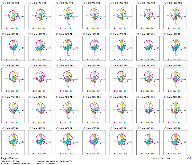
Wideband radiation patterns
This set of Radiation Patterns of a Log Per antenna from 600MHz to 4GHz was measured in one rotation sequence:
Specifications
| VNA | 2 Port full bidirectional | ||
| Frequency |
range accuracy resolution |
400 to 4000 2 5 |
MHz ppm kHz |
| Return Loss | P1, P2 | >15 | dB |
| Generator |
Power Accuracy Resolution Harmonics |
-30 to +5 +/- 1.0 0.5 <-35 |
dBm dB dB dBc |
| Detectors |
Range input attenuator Bandwidth |
-75 to +20 0-30 0.5 – 5 – 10 |
dBm dB kHz |
| Directivity |
400 MHz – 3 GHz 3 GHz – 4 GHz |
55 45 |
dB dB |
| Sweep |
Max size Speed 1-port -4000 pts Speed 2-port -4000 pts Speed 1-port -25 pts Speed 1-port -25 pts Variables
|
2001 1000 2000 17 33 Frequency, Power, P1 P2 attenuator, Bias Voltage, Current Sweeo variables can be combined and nested in a parametric sweep |
Points ms ms ms ms
|
| Software |
Operating System Recommended PC |
Windows XP – Windows 10 Intel I3 or I5 system |
|
Display formats: Source impedance, Port impedance, Return Loss, Forward Loss, SWR, Impedance (mag/ph), Impedance (Smith), Gain (mag/ph/group delay), Gain Polar.
Downloads
| VNA Brochure | VNA Brochure |
| VNA Software | VNA Software and Firmware page |
| MegiQ VNA0440-VNA-0460 User Manual | VNA-0440e and VNA-0460e User Manual |
| VNA Sandbox Measurement | Shows the measurements of the VNA software |
| MigiQ VNA Api Package | Documentation of the MegiQ VNA Application Programming Interface |
| MigiQ VNA Api Package | Documentation and example programs that use the MegiQ Application Programming Interface |
Downloads – Product Information
Excerpts of our VNA Sandbox tutorial that is included with the VSB.
Balanced Calibration Kit Overview
Excerpts of our Balanced measurements tutorial that is included with the Balanced Calibration Kit.
VNA-04×0(e) Product Info and Specifications
Specifications of the MegiQ VNA0440(e) / VNA0460(e).
RMS-0640 / RMS-0660 Specifications
Specifications of the MegiQ Radiation Measurement System.
Software and documentation
VNA Software and Firmware page.
MegiQ VNA0440-VNA0460 User Manual V3.1
VNA0440(e) / VNA0460(e) User Manual.
Documentation of the MegiQ VNA Application Programming Interface.
Documentation and example programs that use the MegiQ VNA Application Programming Interface.
Application Notes
AN100 VNA-0440(e) Measurements
Example measurements exploring the possibilities of the VNA0440 and VNA0440e and the VNA Sandbox.
Some tips how to prevent damage to connectors.
How UFL connectors can be used in VNA measurements.
AN103 Production Antenna Testing
Case report of using the VNA0440 in production testing.
Designing RF inside all metal luminairs can be challenging.
AN105 Contactless Antenna Measurement using a VNA
A technique of antenna measurement using a coupling loop.
AN106 Calculating TIS from TRP
How to calculate TIS when the TRP can be readily measured.
AN107 VNA-0460e Measurement Quality
Assessment of the quality and stability of the VNA-0460e Vector Network Analyzer measurements.

VNA-0440
4 GHz 2-port VNA

VNA-0440e
4 GHz 3-port VNA with bias generator

VNA0460
6 GHz 2-port VNA

VNA-0460e
6 GHz 3-port VNA with Bias Generator

VNA Sandbox

Balanced and UFL Calibration Kit

VNA+ Sandbox Kits
Radiation measurement Sytems