The post Energy-saving with NB-IoT and LTE-M part 3 appeared first on akorIoT.
]]>Energy-saving with NB-IoT and LTE-M part 3 – NeoMesh as a complement to NB-IoT and LTE-M
In this series of three blog articles, adapted from the IoT M2M Times, we take a closer look at the energy consumption of NB-IoT and LTE-M. On their own, these physical layer standards do not deliver energy savings. The IoT developer has to choose the right AT commands and the right protocol with the right strategy for their chosen application. Sometimes we have to do without NB-IoT and LTE-M and take a different path. We hope that you have fun reading and learning.
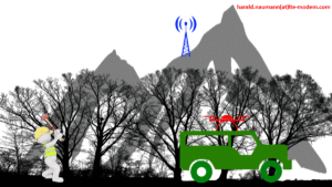
In this the final blog we look at how to complement NB-IoT and LTE-M, double the 10 year battery life and extend the range to the third floor basement of an underground garage or a sewer 50 metres underground. This can be learned from the proven success of Triptec in Germany in doing just that.
Longer operating time for Triptec’s operating hour meters, data loggers and alarm devices
Triptec HL UG was founded in 2001 and operates thousands of operating hour meters, data loggers and fault detectors with the necessary cloud server. Customers include public utilities, municipalities, industrial companies and energy utilities. The goal of their wireless IoT devices is to monitor and optimise the operation of wastewater plants, district heating power plants and machines, for example. The operating hour meters are used to determine the time of use of machines and derive any necessary maintenance. The data loggers record measurement data and transmit it periodically to the cloud. The fault indicators monitor measured variables and trigger an alarm in the event of a fault. A combination of alarm and data logger is common. Up to now, Triptec has used GSM/GPRS modules to send messages or receive control commands at the units. GSM/GPRS belongs to the second generation of mobile radio. 3G was shut down in Germany in the summer of 2021. In Switzerland, 2G was taken out of operation in 2020. None of the three German network operators can promise how long GSM will continue to operate in Germany. Triptec’s customers are therefore pushing for future-proof radio technology. At the same time, Triptec wants to reduce the energy consumption of wireless IoT devices during the redesign and reach new market segments.
Implementation with NeoCortec Sub-GHz-Meshnet in combination with Quectel BG95-M3 (NB-IoT, LTE-M and GPRS) by Triptec
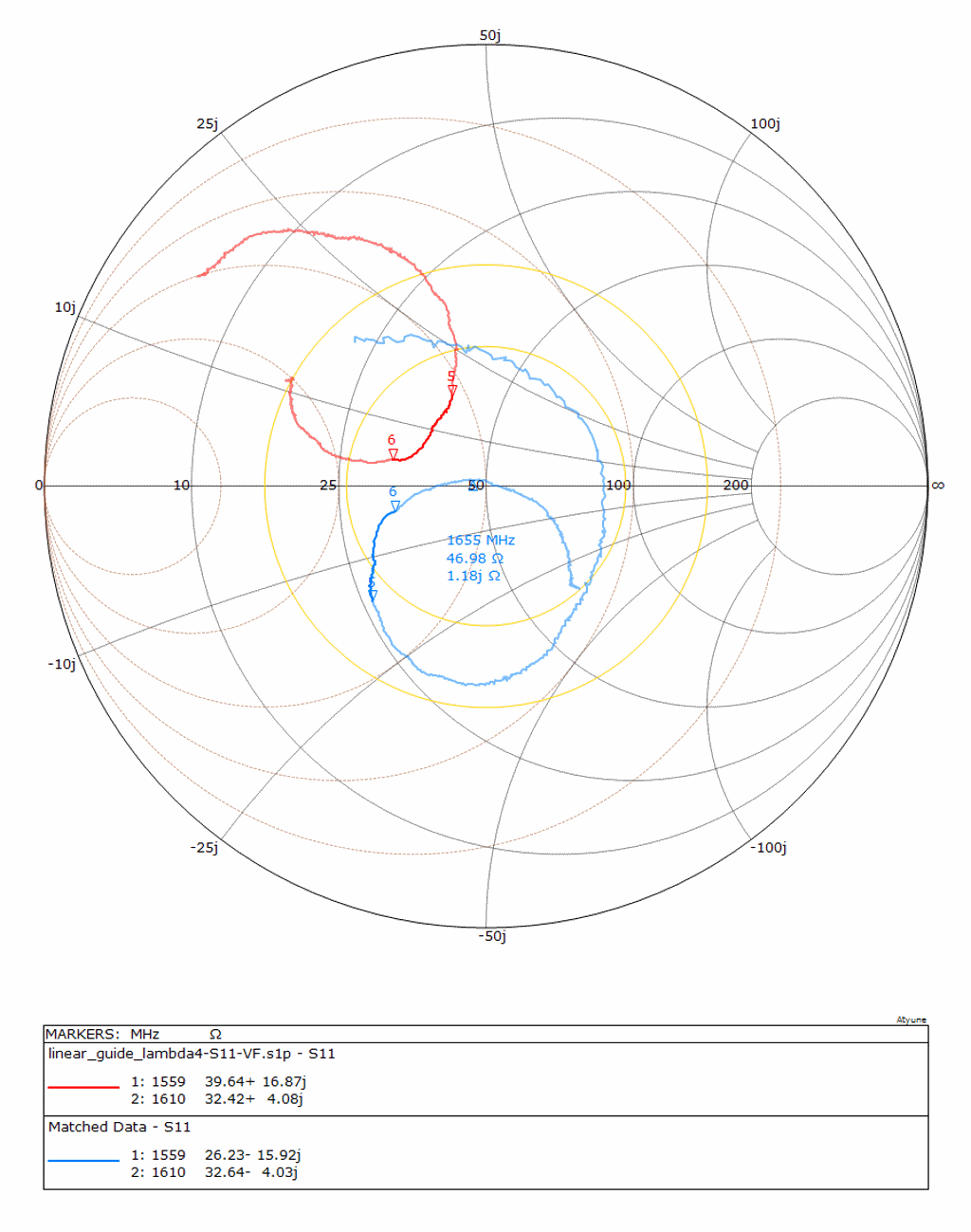
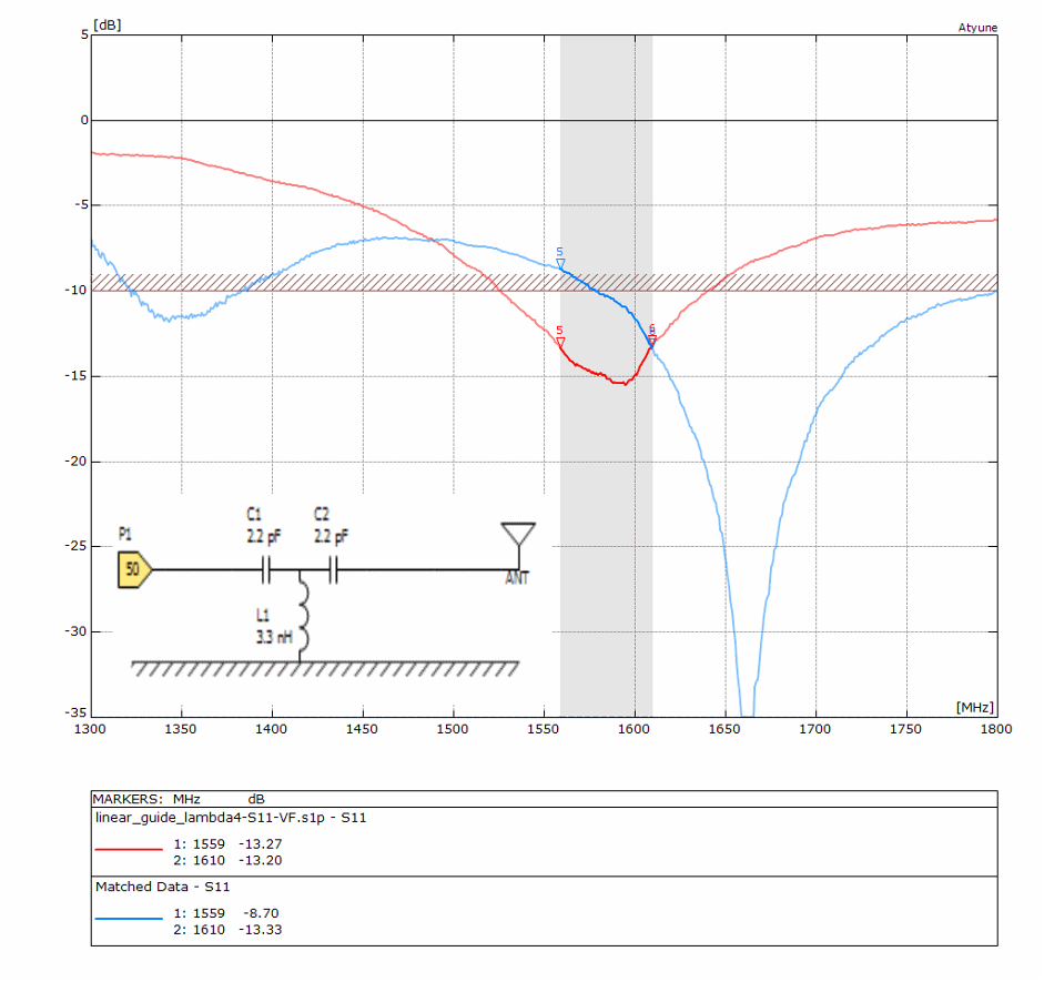
NB-IoT and LTE-M, unlike GSM, were specified from the start for data communication with low energy consumption. NB-IoT and LTE-M use various timers that enable an IoT device from Triptec to be connected bidirectionally. For example, the devices listen to the cellular channel at a variable interval set between every minute to 175 minutes to check if a message arrives. The device can go to sleep, receive nothing and still remain logged on. In the event of a fault, the cellular radio module BG95 is woken up. There is no need to register again with the cellular network, thus saving energy. Furthermore, NB-IoT and LTE-M offer up to 20 dB more link budget than the previously used GPRS. 8 dB corresponds approximately to doubling the range or roughly the attenuation caused by a wall in a building. With 20 dB budget, the user can penetrate 2 more walls and potentially reach into a basement.
The low-power mobile technology NB-IoT/LTE-M has been complemented with a Sub-GHz meshnet from NeoCortec called NeoMesh. NeoCortec drastically reduces energy consumption per node through extremely precise timing. Instead of transmitting 1 to 3 km to the mobile phone mast, NeoMesh transmits up to approximately 100 metres indoors. Outdoors, 500 metres is possible. A message hops from one radio node to the next in a NeoMesh. Each node in the NeoMesh is also a router. In addition, each message is acknowledged to the next node. In the event of a fault, the message is transmitted again in the next cycle on another of the 15 channels. If a node fails, the module in the NeoMesh automatically searches for a new path. All nodes synchronise every 1 to 30 seconds. With a pulse of 30 seconds. With this approach, a node can operate for up to 7 years from 2 alkaline AA cells.
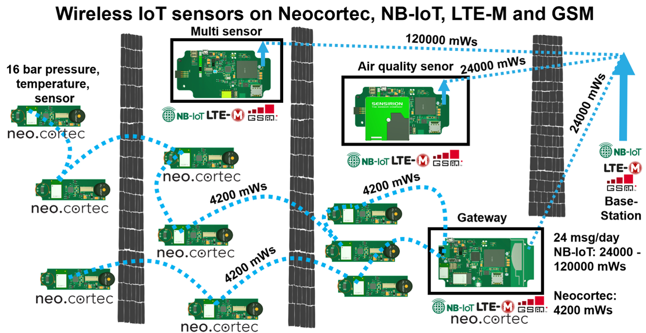
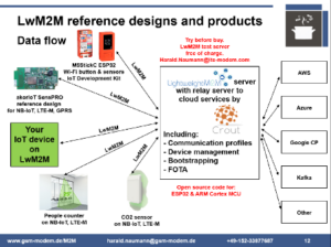
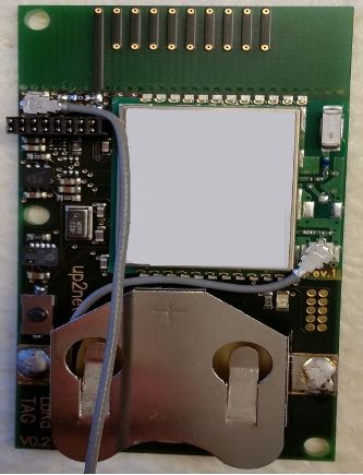
Data flow for stand-alone with NeoCortec NC1000 as pressure and temperature sensor for pipes, multi-sensor for various measured variables, a sensor for air quality and gateway with NC1000 and BG95.
An NB-IoT/-LTE device requires approximately 5200 mWs for a message at long range to the base station (154 dB link budget). One message per hour results in approximately 24,000 to 124,800 mWs per day without acknowledgement, depending on the link budget. With acknowledgement, approximately twice the amount of energy is required. NeoMesh requires only 4200 mWs for the 24 messages including acknowledgement. The gateway is also an edge computer. The MCU is woken up every 30 seconds by the NeoCortec module, writes the measured value to the memory and makes a target/actual comparison. If a limit value is exceeded, the BG95 is woken up and the message is transmitted to the server within 2 to 10 seconds. Since the fault message is the exception, the gateway usually sleeps and transmits the data to the cloud once or twice a day if desired.
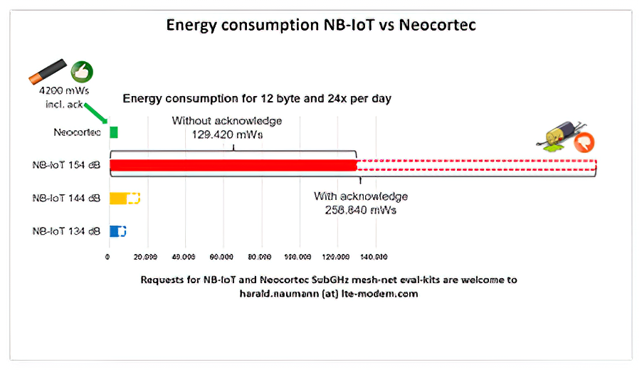 Comparison of the energy consumption of NeoCortec and NB-IoT for 24 messages per day. Source for the measurement series with the LPWAN technologies. Download the study: https://www.akoriot.com/white-papers/
Wilhelm Oelers, CTO of Triptec says: “We compared the known Mesh-Net protocols and in the end found that most of them do not support Sub-GHz. In addition, with BLE-Mesh, ZigBee, Thread or 6LoWPAN, the routers and also the gateway module are not allowed to sleep. NeoMesh from NeoCortec on Sub-GHz helps us to penetrate the walls well. All participants (gateway, router, node) go to sleep at the same time. This allows 2 AA cells to operate for years. In this way, NeoCortec meets Triptec’s demand for minimum energy consumption with a good range in the licence-free 868/915 MHz band. The NeoMesh can be stretched almost as deep as desired into the ground. In a multi-storey car park, sensors in the third basement and deeper are no problem. A sewer is no longer a hurdle. The combination of NB-IoT/LTE-M with NeoMesh means there are no more radio dead spots for us.”
Summary of NeoMesh combined with NB-IoT and LTE-M
PSM, RAI and eDRX of NB-IoT and LTE-M can be combined with NeoMesh from NeoCortec. The IoT developer just needs to combine the right control commands in NeoMesh with the AT commands of NB-IoT and LTE-M.
A NeoMesh Evaluation Kit is available. Please send enquiries to harald.naumann (at) lte-modem.com
The post Energy-saving with NB-IoT and LTE-M part 3 appeared first on akorIoT.
]]>The post Energy-saving with NB-IoT and LTE-M part 2 appeared first on akorIoT.
]]>Energy-saving with NB-IoT and LTE-M part 2 – LWM2M versus MQTT
In this series of three blog articles, adapted from the IoT M2M Times, we take a closer look at the energy consumption of NB-IoT and LTE-M. On their own, these physical layer standards do not deliver energy savings. The IoT developer has to choose the right AT commands and the right protocol with the right strategy for their chosen application. Sometimes we have to do without NB-IoT and LTE-M and take a different path. We hope that you have fun reading and learning.
This second article compares LWM2M and MQTT. In a simple summary: MQTT can do practically nothing and LwM2M can do everything.
So what can MQTT do?
Message Queuing Telemetry Transport (MQTT) can, as the name suggests, only transport data with 14 control commands. Unfortunately, MQTT does not transport the data in an energy-optimised way for battery-operated devices. MQTT is a compromise between energy-saving and safety when transporting data having been developed by IBM for oil pipelines. Compared to the energy-hungry HTTP, MQTT requires less energy. HTTP was developed to transfer web pages based on TCP and therefore does not need to save energy. TCP is inherently very hungry because it repeats packets if there is no acknowledgement. Unfortunately, with MQTT, only the complex page description language HTML has been trimmed and the main problem caused by TCP has not been eliminated. MQTT makes it possible to work on the protocol layer with and without acknowledgements, however the layer below is TCP and continues to acknowledge. In addition, TCP servers have a time-out window that can often not be met via radio protocols leading to further energy-sapping retransmissions. #NBIoT and #LTEM with a latency of up to 20 seconds are difficult to use with high energy consumption. The Power Saving modes of (PSM) with up to 310 hours and Extended Discontinuous Reception (eDRX) of up to 40 minutes cannot be operated at all with MQTT. The developers had a good idea in 1999 and unfortunately missed the chance to develop the MQTT protocol on User Datagram Protocol (UDP) instead of TCP.
What can CoAP do?
CoAP was published 10 years later in December 2009 as “CoAP Feature Analysis draft-shelby-6lowapp-coap-00“. Like MQTT, it can transport data. It was specified as a transmission protocol for use in restricted networks and nodes for M2M applications. These constrained nodes often use 8-bit microcontrollers with little memory. Wireless networks such as 6LoWPAN often have a high packet error rate. The special conditions and packet loss were taken into account in the specification of CoAP from experience in the 6LoWPAN world. CoAP used UDP instead of TCP. It has only four control commands (Get, Put, Delete and Post). UDP does not acknowledge at its protocol layer. An acknowledgement is only made one level higher with CoAP. Within CoAP, commands can be sent with or without an acknowledgement. Because the fill level of a tank or a water meter is sent cyclically, an acknowledgement is usually unnecessary. Packet loss is not critical. Since CoAP on UDP or SMS has no time-out, a few minutes delay with SMS or hours and days with NB-IoT PSM and NB-IoT eDRX are no problem. NB-IoT Release Assistance Indication (RAI) immediately switches off the receiver after sending and thus fits perfectly with CoAP without acknowledgement. CoAP is in perfect symbiosis with NB-IoT and LTE-M. The first version of the specification had 14 pages, but had grown to 110 pages over several adaptations by 2013.
What can LwM2M do?
LwM2M v MQTT
LwM2M, unlike MQTT and CoAP, is much more than just a transmission protocol for data. In order for LwM2M to perfectly serve the new low-energy radio protocols NB-IoT and LTE-M, CoAP/UDP and SMS were chosen in version 1.0. This ensures that NB-IoT can be used taking advantage of energy saving modes PSM, eDRX, and RAI. In the newer versions of LwM2M, LoRaWAN, CoAP/TCP and even MQTT have been added. Devices with MQTT can thus be easily integrated into LwM2M. One of the key features of LwM2M is device management. Since LwM2M was influenced by mobile network operators at the OMA, their experience in managing wireless phones has been taken into account. Registration with the LwM2M server is possible very securely in various ways. The commissioning of a device with bootstrap is also standardised under LwM2M. Necessary FOTA (Firmware Over The Air) updates are also managed by the server. The communication of a device is standardised with profiles and resources. Through the mandatory profiles Security, Server, Device and Location, any LwM2M device from any manufacturer can communicate with any LwM2M server on our beautiful blue planet. After successful registration, the LwM2M server enquires and then knows whether it is talking to, for example: a water meter, presence detector, level meter or tracking device. A single device can also support several profiles in parallel providing even greater flexibility.
Summary LwM2M versus MQTT
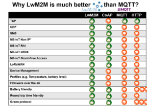
LwM2M v MQTT Feature table
LwM2M supports many protocols for transmission and was first specified on CoAP/UDP. Unlike MQTT, it was planned from the beginning to support devices with batteries and low energy consumption. LwM2M handles device management, bootstrapping, firmware update over the air and communication via profiles. MQTT does not offer all this. MQTT has never been optimised for lowest energy consumption and nothing is regulated and standardised except transport. Any company aiming for extensive digitalisation has a good starting point with LwM2M.
Perhaps we will soon see the launch of a rocket to Mars, with firmware updates via LwM2M. The transit time of about 3 to 22.3 minutes from Mars to Earth is no hurdle for LwM2M. Even signals from Neptune with a 4-hour delay can be solved with this genius protocol.

“Can you hear me Major Tom?”
The post Energy-saving with NB-IoT and LTE-M part 2 appeared first on akorIoT.
]]>The post Energy-saving with NB-IoT and LTE-M part 1 appeared first on akorIoT.
]]>Energy-saving with NB-IoT and LTE-M part 1 – NB-IoT / LTEM versus GSM
In this series of three blog articles, adapted from the IoT M2M Times, we take a closer look at the energy consumption of NB-IoT and LTE-M. On their own, these physical layer standards do not deliver energy savings. The IoT developer has to choose the right AT commands and the right protocol with the right strategy for their chosen application. Sometimes as a result we have to do without NB-IoT and LTE-M and take a different path. We hope that you have fun reading and learning.
In this first article we compare NB-IoT/LTEM with GSM. In a nutshell, GSM was developed for voice communication and NB-IoT / LTEM was developed for data transmission, the different design objectives play out clearly in IoT applications to the advantage of one approach.
So, what can GSM do?
The original goal of GSM was a digital radio network for voice communication without the known problems of analogue radio networks. All carriers for transmitting data were added later.
In 1979, the 900 MHz frequency range was reserved for an unnamed mobile radio system for voice communication. This range was later extended to 1800 MHz in Europe and 850 MHz and 1900 MHz in the USA. In 1982, the CEPT (Conférence Européenne des Postes et Télécommunications) set up a working group called the “Groupe Spéciale Mobile”, or GSM for short. The goal was to develop a European mobile radio system. With the later worldwide spread of the technology, the meaning of GSM was changed to “Global System for Mobile Communications”. It was not until 1995 that fax, Circuit Switch Data (CSD), Short Message Service (SMS) and other functions were added in a second phase for data transmission. The packet-switched data service General Packet Radio Service (GPRS) was only added in 2000. GPRS enabled access to the Internet. After that came EGPRS.
Saving energy with GSM/GPRS
In order for a GSM/GPRS device to communicate it must be switched on. If an IoT device based on GPRS stays switched on in receive mode, it requires a constant current of 5 mA. With this current being continuously drawn, the battery is drained after only a few days. The only way to reduce energy consumption is to switch off the device. If the IoT device is switched off, an energy-hungry re-registration to the GSM/GPRS network is necessary when it is switched on again. An IoT device based on GPRS therefore can only operate in three modes: switched on to receive, switched on to transmit and switched off.
So what is NB-IoT?
NB-IoT is a radio network within a radio network. It is operated in the same frequency band as LTE. NB-IoT was specified from the start to operate on battery power and cannot transmit voice communication.
The history of NB-IoT from 2014
In 2014, Neul, a VC-based startup in Cambridge in the UK came up with the idea for a scalable, secure, robust and economical region-wide radio technology for network operators. For this purpose, the radio protocol for the licence-free band called Weightless was selected by the company. The existing protocol was adapted to use the licence-required bands of mobile radio. The goal was network services for small devices with low power consumption and connection to the cloud. Compared to GPRS, this new technology had a 20 dB higher link budget and thus better network coverage. The radio technology could operate in any frequency band below 1 GHz. Such a Neul-Weightless network required a frequency spectrum of only 180 kHz operating as a network within the network. This meant that a GSM subcarrier or 200 kHz from within the LTE spectrum was enough for it to operate. Neul offered small, powerful radio modules and the base station.
If you look closely, you can see the NB-IoT specification in the wording. NB-IoT uses only 180 kHz in a free spectrum within the LTE frequency band for 12 channels. The 20 dB greater link budget than GPRS is also found in NB-IoT. Huawei recognised the benefits of Weightless and bought Neul in September 2016 for £25 million. The world’s first NB-IoT chipset called Boudica 100 was launched by Huawei subsidiary Hisilicon in December 2016.
In 2022, we have already progressed to third generation NB-IoT chipset. In the paragraphs that follow we will explain how NB-IoT saves energy.
Power Save Mode PSM
NBIoT_LTE-M Tx with RX paging after Tx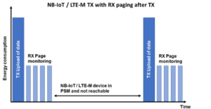
In PSM mode, the radio module is not completely shut down and the memory with the data for logging into the NB-IoT is not erased. With the memory active, the NB-IoT requires only 3 uA of continuous current. Completely shut down, it also requires approximately 3 uA, so there is little penalty to keeping the memory active.
The NB-IoT module informs the NB-IoT base station that it will shut down and stores the registration data. The NB-IoT base station acknowledges the request to shut down and also stores the registration data. The NB-IoT then enters PSM mode and is no longer accessible. The NB-IoT device can be woken up by the microcontroller at any time in the case of an event. In contrast to the first registration (attach), with the data preserved the new registration (called reattach) requires significantly less energy than the original attach.
Release Assistant Indication RAI
NB-IoT/LTE-M TX RAI energy consumption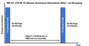
With RAI, the NB-IoT network is informed that no receipt of data is expected after transmission. Water meters, bins for recyclables and many other IoT sensors do not require an acknowledgement after sending data. If the packet containing the status of the meter or the fill level is lost, it doesn’t matter because a new status is transmitted 12 or 24 hours later anyway. Shutting down the receive window saves up to 50 % of the energy of a data packet. If alarm messages with acknowledgements are required, RAI can be switched on and off dynamically. To use RAI, NB-IoT with UDP or CoAP/UDP must be used. TCP and MQTT based on TCP cannot work because the protocol requires acknowledgement. All protocols based on TCP are therefore not suitable for energy-saving with RAI.
Extended Discontinuous Reception eDRX
NB-IoT/LTE-M energy consumption with eDRX over time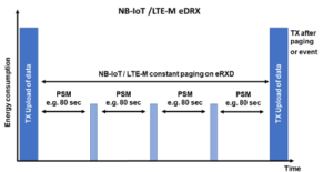
The eDRX operating mode enables continuous receive operation. The approach is not new and has been used with pagers for decades. A Pocsag pager wakes up briefly every few seconds and checks whether a message is received. If it recognises from the group address that the message is not for it, it does not read in the complete address and immediately aborts the receive operation. With NB-IoT, there is also periodic continuous receiving (paging) with eDRX. In contrast to Pocsag, the reception window for paging is not statically set to seconds but can be dynamic from 20.48 to 10485.76 seconds (~175 minutes). The NB-IoT device informs the base station of the timer for the eDRX, receives an acknowledgement and is then periodically reachable.
NB-IoT energy saving summary
NB-IoT, like Bluetooth Low Energy, NeoMesh and Pocsag, requires little energy. The four wireless technologies save energy by switching off in intelligent ways. Switching off and not receiving saves the most energy. NB-IoT, Bluetooth Low Energy, NeoMesh and Pocsag pagers can receive continuously with little energy because receiving is synchronised via precise timers. This is called eDRX in NB-IoT. PSM is just a smart power down without really switching off. RAI is just a smart send without opening a receive window.
This flexibility means that the IoT developer must dynamically switch on or switch over the functions PSM, RAI and eDRX themself based on the requirements of their target application. Everyone must find the right strategy themselves. The same applies to searching for the radio network or switching from NB-IoT to LTEM and vice versa. LTEM modules offer the same timers. When to switch and how can be read in my guide to NB-IoT, LTEM and GSM which will help you find the best strategy for your IoT application. Enquiries about the guide can be sent to harald.naumann (at) lte-modem.com
The post Energy-saving with NB-IoT and LTE-M part 1 appeared first on akorIoT.
]]>The post Rescue from the air for lone workers appeared first on akorIoT.
]]>Rescue from the air – IoT Project 1
Injured worker using drone to call for help
In this issue of the IoT M2M Times, we explain a complete IoT project for the first time. We explain the project including the selection of radio modules and antennas. Telling this story is possible because it is an EU funded project and have permission to document it.
Table of contents:
- Rescue drones for forest workers
- Cellular radio
- SIM card
- LwM2M Server
- 5G/LTE antenna
- Bluetooth
- DECT
- LoRa 2400
- Radio direction-finding
- Patch antenna for 2400 MHz or 1900 MHz
- Notes on the project
Rescue drones for forest workers
Working in the forest involves a high level of risk. Accidents are usually characterised by severe personal injuries. In order to increase the chances of the injured person surviving, quick initiation of first aid measures is necessary. Direct routing of rescue workers to the scene of the accident is essential. Lone working is forbidden in cases of extreme risk. If an emergency occurs and the casualty does not have a functioning emergency call system or there is no connection, no emergency call can be made. In the worst case, this can mean that the accident is only discovered after several hours delay.
In Germany’s largest low mountain range, the Black Forest, there is very often no connection to a mobile phone network.
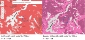
Coverage of Vodafone and DT networks in the Black Forest
To tackle this problem, the German inventors of Focus Infocom in Darmstadt had an awesome idea that came within the scope of an EU funded project. Each forestry worker’s vehicle will be equipped with a drone. In an emergency, the drone rises, flies over the injured person and establishes a connection to the mobile phone network. The connection via a voice call on the 5G/ LTE network always works. This has already been tested with a German drone manufacturer using normal Android. Focus Infocom then contacted us.
Our task now is to design a link with for a voice connection from drone to the ground. As part of this we are given the lattitute to select all the radio modules and antennas that will be required.
Cellular radio:
A PCIe card with 5G and LTE is used. This makes it possible to change the cellular module at any time and adapt it to other countries. The LTE / 5G drone with a ground to air relay function is suitable for many other applications. The relay radio can be set up in different ways. Using a PCIe card, the drone can be equipped modularly and reconfigured with ease for different field use cases.
SIM card:
SIM cards from Crout www.crout.de are used for the SIM card. SIM cards from Crout can receive profiles remotely, just like an iPhone. When it is switched on, the drone checks the country and then receives the right profiles from the local network operators. At a height of 30 to 40 metres, you can safely reach any of the country’s 3 5G/LTE radio networks.
In the profiles, we can specify the preferred sequence of the 5G/LTE networks for an attempted connection. The SIM card is not roaming in Germany but is basically three SIM cards in the form of one. In total, there can be up to 7 SIM cards on one SIM . When the drone goes up at the start of work and a test is carried out, it is possible to check which network is the better network for that location. This network is then set as the default. The settings for the default can vary from region to region.
To avoid problems in border areas, foreign networks are blocked immediately so that the calls are not routed back to Germany via third countries.
LwM2M server:
LwM2M application examples
We have chosen LwM2M from Crout for the protocol. Crout thus supplies not only the SIM card but also the test server for LwM2M.
Unlike MQTT and CoAP, LwM2M is much more than just a transmission protocol for data. One of the remarkable features of LwM2M is device management. Since LwM2M was co-influenced by mobile network operators at the OMA, their experience in managing wireless phones has been incorporated. Connection and Logon to the LwM2M server is possible in various very secure ways. The bootstrap start-up of a device is also standardised under LwM2M. Necessary firmware updates are also managed by the LwM2M server.
The communication of a device is standardised with profiles and resources. Through the mandatory profiles Device (/3), Connectivity monitoring (/4), Firmware update (/5), Location (/6), any LwM2M device from any manufacturer can communicate worldwide with any LwM2M server on our beautiful blue planet. After successful registration, the LwM2M server asks which profiles are supported and then knows whether it is a water meter, presence detector, level meter or tracking device, for example. An LwM2M device can also support several profiles in parallel.
For the LwM2M server, the rescue drone is a kind of router or also a kind of locating device. All functions required by the rescue drone are already specified via the LwM2M protocol. The project team can therefore immediately focus on programming the application. Everything else is already specified through LwM2M.
5G/LTE antenna:
The 5G/LTE MIMO antenna will be a classic PCB antenna integrated into the main PCB of the 5G/LTE relay located below the drone. This saves the purchase of LTE antennas and reduces the delivery time to 0 days and reduces the cost to €0.
There are several options for the voice connection:
Bluetooth:
For Bluetooth audio, there are ready-made Bluetooth headsets that can be worn under a helmet. The range of Bluetooth is limited to 10-50 m in the original specification.
If you take a closer look at the transmission power and the sensitivity, you will notice that the free-field range is much greater. Of course, trees in the forest are an obstacle to radio waves, but we have a similar situation in buildings. A wall dampens radio waves, but we know that Bluetooth signals can still be received through a wall.
The actual attenuation of radio waves at 2400 megahertz is best determined in a field test. For this purpose, classic Bluetooth modules with the AT command interface are operated in data communication mode and a message is sent from the ground to the drone in the air. The drone measures the receiving level and sends this back to the Bluetooth module on the ground. The receiving level is also measured there. This means that in one ping, the losses through the tree canopy are determined twice.
Since Bluetooth data transmission is very fast, a large number of measured values are recorded in a short time. Directional planar antennas are used to optimise penetration.
In real operation, a Bluetooth audio connection is then used. Since hands-free devices and headsets for employees in industrial plants, oil platforms and also forestry workers are already available on the market, the development of dedicated intercom device on the body of the forestry worker can possibly be saved.
DECT:
Ready-made headsets and hands-free devices are already available on the market for this radio standard as well. Therefore, the development of an intercom device can also be saved.
The field test procedure is the same as for Bluetooth. The device on the ground sends a signal to the aircraft in the air and the latter acknowledges back to the ground. Again, two measurements are taken.
LoRa 2400:
LoRa is very well known in the Sub-GHz range. There is now a LoRa version for 2400 MHz. With a simple voice codec, it would be possible to transmit voice signals via LoRa. The achievable link budget is certainly greater with LoRa 2400 MHz than with Bluetooth. But if Bluetooth or DECT meet the requirements, then a development based on LoRa is not necessary.
For the relay station on the aircraft, no great effort is required for the audio codec. Since a Raspberry Pi is planned for the relay station, standard codecs can be used for audio transmission.
For the headset under the helmet, custom development would be necessary. However, since there are German companies that have already developed intercom devices with Bluetooth and DECT, such a custom development is technically not a problem.
Radio direction finding:
A special antenna can be used to determine the direction and angle of the injured person on the ground. LoRa in the 868 MHz range may be used in this case. This method is already in use for tracking people buried under snow avalanches. Although a much lower transmission frequency is used , the measuring method would be the same. The measuring antenna on the aircraft receives the output signal twice. The direction to the injured person can be determined via the field strength and the phase shift.
Radio localisation is only necessary, however, if the audio signal is too strongly attenuated by the trees and the aircraft has to take up a position as precisely as possible above the injured person. Another advantage of radio direction finding is that it can be used to determine a more accurate position of the casualty.
GNSS:
The aircraft is equipped with a GNSS antenna and a GNSS receiver. Because the drone is in the air, receiving the satellite signal is not a problem. The GNSS antenna will probably be a classic ceramic patch antenna mounted on the main PCB.
Patch antenna for 2400 MHz or 1900 MHz:
A Patch Antenna
To increase the maximum link budget, a patch antenna with an antenna gain of 10 dB is used. This patch antenna has circular reception. Because of the circular polarisation, it does not matter whether the antenna on the ground is polarised horizontally or vertically. The received signal at the relay station of the drone is then only influenced by the attenuation of the air, the attenuation of the trees and the body attenuation of the injured person.
Notes on the project:
The rescue drone is a truly innovative projects for a unique application. The use of radio technologies is extensive: In addition to the 5G module, Bluetooth will probably also be used for audio transmission; determination of position via GNSS is obligatory; the LoRa module at 868 MHz will make it possible to determine the position of an injured person or an object at a great distance.
For the forestry workers, GNSS and Lora are not necessary for the project, because the service vehicle launching the flying drone is nearby.
As already mentioned, the rescue drone can be used for many other applications. Because the radio modules are planned in a modular way, further interesting applications in wireless IoT can be implemented by swapping the modules.
The next special aspect of this project is that the project manager at Focus is a former colleague with whom I worked at Ascom 35 years ago. For me, the first job was in the world of wireless electronics. The project manager was also very new to the world of wireless data transmission at the time. The word IoT and the word M2M didn’t exist yet. We used both standard radios and trunked radios to transmit data at 1200 bit/s to send messages from one place to another. We were pioneers in the Internet of Things for 35 years without knowing that IoT would eventually be specified.
The lesson here is that if you keep your current contacts, you can work with former colleagues to realise an innovative IoT project 30 years from now. This project came in the fourth quarter of 2021, but the crazy thing is that, just like busses, a second 35-year-old contact came along to start a very innovative project with me in the fourth quarter. I have permission to write about this project as well. Stay tuned for that story.
Your wireless IoT projects
If you have a need for a custom antenna or are just starting a new innovative wireless IoT project, I would love to hear from you. Wireless IoT and antennas are my mission. Thank you in advance for your request to harald.naumann (at) lte-modem.com
The post Rescue from the air for lone workers appeared first on akorIoT.
]]>GSM / NB-IoT PIFA antennas that fly
As any antenna designer or an informed person who has read the IoT/M2M Cookbook knows, metal and antennas do not play well together.
Many times, we are contacted by frustrated designers who find that the antennas they are using don’t work as advertised because the datasheet parameters are measured in free space.
In our cookbooks we describe in some detail the techniques you can use to keep your antenna performance on track, either through careful construction of your PCB layers, vias and your ground plane, or being mindful of the effects of metal objects such as batteries and other influences, such as the Epsilon r of your proposed enclosure.
But what do you do if you can’t avoid mounting your antenna on or near metal? One approach that we are exploring is allowing the antenna to take to the air. In order to give your antenna wings, you don’t need a popular energy drink, what you need is an air gap (Epsilon r = 1) to the metal of 5-8 mm or less if your material’s Epsilon r is greater, for example plastic at 2.8 or FR4 at 4.2.
There will be some effect on the length of antenna radiator required and a narrowing of bandwidth, but the transmitter will work, and the akorIoT team can help you with the final configuration and tuning of the matching circuit to get you the performance and battery life that you need for your IoT application.
Starting from sketch on a restaurant napkin, as all good ideas do:
A picture tells a thousand words. I do not remember how often I have drawn such a sketch at a customer’s office. It is time to stop re-inventing the wheel and to create an online antenna proposal gallery.
In the photograph below the GSM / NB-IoT PIFA antenna is “flying” over the ground plane by sitting on a raised plastic platform. If the antenna shape has taken flight, then as mentioned earlier the metal chassis of a car, machine or sea conatiner will not interfere greatly with the antenna. The same antenna types can be used for dog collars, belts, surfboards or skies. Such GSM / NB-IoT PIFA antennas will radiate directionally. If the antenna is mounted on what is effectively water (human wrist, dog collar, ice etc. because a living being is mainly water), then it makes no sense to have an antenna that radiates omnidirectionally because radio waves and energy will just be wasted on absorption by the water. The metal or water in the vicinity would strongly influence an omnidirectional monopole antenna. An antenna which is above the ground plane does not “see” the metal of the container or the water and is therefore not affected. The drawback is that such unidirectional antennas are not available off-the-shelf. Such PIFA antennas need customisation.
Last week a big package of antennas reached me. Step by step over the coming posts I will make the description of the antennas public.
The picture above shows an antenna for GSM and UMTS in mid-flight over the ground plane. The plastic enclosure or the antenna has an estimated size of 32 mm x 40 mm x 8 mm including the plastic clips. Such an antenna radiates directionally, perfect for our people or pet tracker. It is also a good approach if you plan to screw the tracking device onto metal surface (e.g., metal container or metal bin). The PIFA antenna has two metal contacts. One of the pins is the feeding line and the other one will be wired to ground plane. This shorting to ground is standard for inverted F antennas or planar inverted F antennas. The two contacts pins of the antenna will connect to spring-loaded contacts on the PCB. The pin on the left is positive for the feeding line while the pin on the right is negative and connected to the ground plane of the main board. Free space is REQUIRED with a gap of 3 – 5 mm at the point of the spring-loaded contacts or the pogo pin on the main board. An additional metal ground plane is not required for this design because this kind of antenna uses the whole main PCB as part of the antenna structure.
This antenna is originally designed for 3G cellular bands for a portable GPS tracker. The metal on the plastic enclosure is made by laser direct structuring (LDS). A customisation of the antenna structure is also possible. Such “flying” antennas can also be cut from white lead with a laser or water jet. Also etching is possible. The metal is then bent and fixed in place with a plastic holder. For a prototype, all you need is an empty can of the well-known energy drink mentioned above, a pair of scissors and some experience in antenna design. Simply cut it out, bend it, solder it in and then measure it. Even when soldered and bent, the antenna can still be reworked with the scissors. If too much is cut off, desolder the antenna and start again. When you have used up all the first cans of the energy drink, you take the red cans of the brown caffeinated lemonade from the USA. If you used up the red cans and get frustrated then do not hesitate to ask for customised antennas to harald.naumann (at) lte-modem.de .
The post GSM / NB-IoT PIFA antennas that fly appeared first on akorIoT.
]]>The post Which IoT protocol do I use? Here is the answer appeared first on akorIoT.
]]>Which IoT protocol do I use?
Very recently a significant new customer has asked us to design a combined LoRaWAN / Cellular (LTE-M/ NB-IoT) board. Cellular is pretty new.
Q: I am currently selecting a suitable cellular modem. The idea is that we will run sensor applications on a specific (STM32L4… ) MCU, which will communicate with either a cellular modem or LoRaWAN modem via an AT serial interface (not simultaneously). This is a departure from the single MCU application + LoRaWAN stack that we use now.
Part of the design is of course identifying an application-level protocol. There is one discussion on your site where you recommend CoAP for NB-IoT. We will be starting with LTE-M, using NB-IoT a bit later. Rather than CoAP (which I’ve used before) there is another choice now MQTT-SN over UDP, which is being promoted extensively by one manufacturer at least. As a fan of MQTT anyway, going the MQTT-SN route looks like a really good fit.
So I was interested if you had any thoughts on using that over CoAP?
IoT protocol comparison
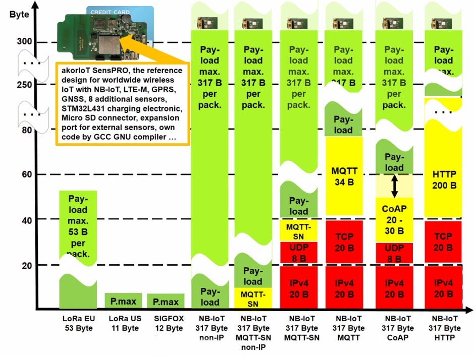
The main difference between MQTT-SN and CoAp is that the former requires a broker. This means that its client nodes have less complexity, however the need for a broker could make a system more complex to integrate into an existing infrastructure. Overall energy requirements are similar as both work over UDP (see: Performance Evaluation of CoAP and MQTT_SN in an IoT Environment Mónica Martí, Carlos Garcia-Rubio and Celeste Campo. 13th International Conference on Ubiquitous Computing and Ambient Intelligence UCAmI 2019, Toledo, Spain, 2–5 December 2019)
The above graphic shows the number of bytes required to transmit a message. The red area shows the necessary protocol overhead of the carrier: TCP/IP or UDP/IP. TCP/IP specifies that the telegram must be acknowledged automatically after transmission. If the transmission is negative or there is no acknowledgement, TCP/IP repeats the message several times automatically. However, if the acknowledgement is impossible for technical reasons, TCP/IP burns energy and bandwidth unnecessarily.
NB-IoT is quite a new radio technology, however, data was transmitted via radio before NB-IoT. A praiseworthy example is 802.15.4 with 6LoWPAN. 6LoWPAN is a transmission protocol on IP (PPP) and was specified for radio and wired communications by small low powered devices. The layer above it is UDP (not TCP). If a radio channel is disturbed, then it generally makes no sense to start a new transmission of the telegram. UDP does not send an acknowledgement and does not expect an acknowledgement. If you elect to use UDP, then the acknowledgement must be done in the protocol layer above it. The protocol layer above UDP is usually CoAP in the case of 6LoWPAN, CoAP requires that a telegram is sent (with or without acknowledgement). This means that the programmer himself can decide whether he needs an acknowledgement or not. We serve a customer who has been using GPRS for over ten years and transmits his position data with a proprietary protocol based on UDP. 98% of his sent messages reach the server. Since the customer transmits every five seconds, the loss of a single message is unimportant. If you transfer this thinking to your design and use CoAP, then you can confidently do without the receipt, because 98% of the sent messages will arrive on the server. LWM2M is a protocol from the Open Mobile Alliance and is a layer above CoAP.
The structure as a glance
PPP => UDP/IP => CoAP => LWM2M
PPP => UDP/IP => MQTT-SN => not defined
PPP => TCP/IP => MQTT => not defined
In the akorIoT Group, we decided to use CoAP and defined the protocol layer above it ourselves. In addition, we have chosen an encryption method that is extremely secure and thus avoids the risk that third parties can read our data traffic. The encryption is from end-to-end and therefore neither the NB-IoT network operator nor other bad guys can read our communications.
The most convenient way with the highest energy waste is HTTPS with the JASON open standard file format. The most inconvenient way with the lowest energy consumption is NB-IoT NON-IP with its own protocol. It is also the way with the most barriers because NON-IP is not supported by all network operators. If you plan a local product for example only for Germany then you can use NON-IP without problems. If you plan like the akorIoT GROUP does Internationally, then NB-IoT with CoAP is a good approach. Whether you then use LWM2M as an application layer above or your own protocol layer, is up to you. LWM2M is a convenient approach, because not only the profiles of the telegrams are regulated there, but also the login to the server and the device management. LWM2M can also be used with SMS or based on LoRaWAN. The latest version of LWM2M is supporting TCP/IP as well.
The net is that CoAP does not expect an acknowledgement, or CoAP accepts an acknowledgement with extremely long elapsed time. By contrast, long acknowledgement coupled with TCP/IP and its compulsion for receipts resulting in multiple resends will be the death of your battery.
I hope, I could bring a little light into the darkness with my graphics. Unfortunately many people still confuse the bearer and the protocol layers above the bearer. I, therefore, recommend that you take a quick look at the OSI layer model even if the TCP/IP or UDP protocol does not follow the layer model exactly.
The post Which IoT protocol do I use? Here is the answer appeared first on akorIoT.
]]>The post Which LPWAN do you use for an emergency call button? appeared first on akorIoT.
]]>
First of all, we have to establish whether the mobile emergency call button is to be used locally in a building, on a company campus, or nationwide in a European or a non-European country. In this article, we will limit the use of the mobile emergency button to Germany however, this local design can easily be transferred to other countries.
A Nationwide mobile emergency call button for Germany
For a nationwide mobile emergency call button for Germany, NB-IoT with a fallback to GSM is currently the best for future-proofing. Since April 2020 national roaming for NB-IoT has been available in Germany from Deutsche Telekom and Vodafone. The emergency call device therefore has access to two parallel but independent NB-IoT networks. Furthermore, there are now very inexpensive NB-IoT modules offering GSM fallback. With the addition of GSM such an emergency call system can access three independent GSM networks and as a result an NB-IoT/GSM combination module can achieve a fivefold network redundancy in Germany.
Emergency call button locally on a company campus
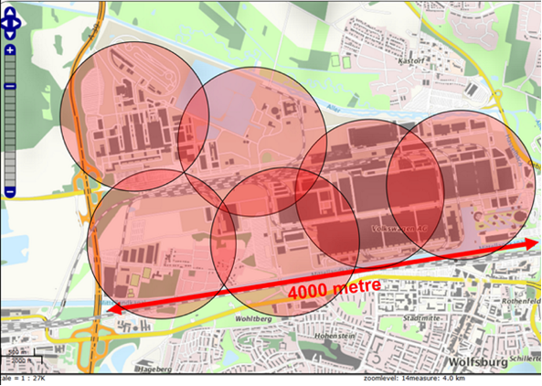
If a mobile emergency call system is needed locally on a company campus or in a building, LoRaWAN is a suitable solution. LoRaWAN offers us inexpensive gateways including an antenna for outdoor installation for about € 500. The frequency range for LoRaWAN is license-free in Germany. For the Volkswagen plant in Wolfsburg, fewer than ten gateways are needed to cover the entire plant area including inside the buildings.
Indoor emergency call button with localisation
If you need a mobile emergency call button which also offers a localization via the field strength in the building, Neocortec with its SubGHz Meshnet is suitable. With Neocortec the radio network is built up completely independently. Each node is also a router. Due to the high link budget and the good penetration through walls, only a few permanently installed nodes are necessary to cover a building completely. These permanently installed nodes are called anchors. Each mobile node synchronizes every second up to every 30 seconds with 3-12 neighbouring nodes. The field strength is also transmitted to the neighbours during synchronization. The gateways in such a SubGHz Meshnet cyclically receive the field strength values of the nodes to their neighbours. Since the locations of the anchors are known, the approximate location of the mobile nodes can be calculated.
During a test in our office in Munich, we established a radio link from the meeting room on the left side of the building to the offices on the next higher floor on the right side of the building. In doing so, we passed the floor/ceiling and four walls and still had plenty of link margin-left.
For a mobile emergency call system in a building or on an oil platform I would recommend SubGHz Meshnet. If you limit the number of neighbours to three and set the synchronization time to 30 seconds, a radio module from Neocortec works on two standard AA cells with 2500 mAh for 7 years including 170 messages per day with 21-byte user data per message.
Each message from a node to a neighbour is acknowledged at the node. This means that an alarm message is acknowledged from end-to-end. In addition, cyclic synchronization means that the gateway knows which nodes are located in the network. If a node fails to appear during synchronisation several times, the node has been lost or has left the network. If you compare this with NB-IoT and LoRaWAN, you will find that there is no cyclical synchronisation of the stations in the network. A missing subscriber is not detected and a failed emergency call button does not work anymore and cannot transmit a message in case of emergency.
This unique SubGHz Meshnet changes the radio channel with every connection and hops across all the European 868 MHz bands. If a packet is lost during transmission to a neighbour because the radio channel used is interfered with, the message is repeated on another radio channel. The radio module selects the 3-12 neighbours randomly. If 50 participants are visible in a radio network with 500 participants, then the participants with the highest field strength are not selected but a random selection is made. This means that two or three participants in the same room may see the same 50 neighbours but select their route to the gateway completely differently. Since all 500 participants in the network do this, the radio network is very evenly balanced.
A combination of SubGHz Meshnet and a NB-IoT/GSM combination module provides perfect indoor coverage including automatic detection that the subscriber is no longer present in the SubGHz network plus perfect fivefold redundant coverage outside the building or company campus.
Emergency call button with other LPWAN technologies
In the LPWAN Cookbook, the author compares the well-known LPWAN technologies NB-IoT, LoRaWAN and in addition to SubGHz Meshnet and comes to the conclusion that in many cases SubGHz Meshnet from Neocortec needs less energy and has a much higher operational reliability.
In the community of Kirchheim with its twelve villages, none of the villages is completely covered by Sigfox indoors (blue area). But in all twelve villages you can make a phone call with your GSM phone. In addition, in the community of Kirchheim, both NB-IoT network operators offer more or less good network coverage. A SubGHz Meshnet distributed over all twelve villages for 3600 inhabitants in many houses is probably not economical. In order to guarantee a connection, every second or even third streetlight would have to be equipped with an base station. If all streetlights are equipped with a SubGHz Meshnet from Neocortec to monitor the function of the streetlights and to send control commands, this existing Meshnet could be used for other tasks like an emergency call system.
Twelve gateways worth € 500 installed by the voluntary fire brigade would be economical if enough participants in Kirchheim wanted to use the private LPWAN. However, NB-IoT and GSM already offer five-fold redundancy at most locations without the need to install a new network. NB-IoT, GSM and also LoRaWAN offer the possibility to acknowledge an emergency call as often as you like per day. Sigfox works in the upload without automatic acknowledgement and offers in the download only four messages with 8-byte acknowledgement per day. Sigfox, therefore, offers the worst network coverage for the community of Kirchheim and, on top of that, the most insecure connection quality, because you have to do without the acknowledgement of the message after four messages per day. I can therefore not recommend Sigfox for emergency call applications.
The post Which LPWAN do you use for an emergency call button? appeared first on akorIoT.
]]>The post GNSS Antennas and Recycling appeared first on akorIoT.
]]>
Everybody talks about protecting the environment and recycling. The nail antenna from the land of poets and thinkers (Germany) follows this trend. We’ve hit the nail on the head with this design. We don’t need a new nail – no we use old, superfluous, rusty nails and recycle them into valuable, perfect GNSS antennas. This nail antenna was tuned without using a Vector Network Analyser (VNA). To adjust the nail antenna you only need a belt grinder. You shorten the nail with the saw to approximately Lambda/4, check the number of visible GNSS satellites in the NMEA string and then further shorten the nail by grinding it. We do this until we see a maximum number of satellites in the sky. And as you can see, we are saving twice because we use old nails as antennas and save money on the purchase of an expensive VNA. If you don’t have a belt grinder, you are welcome to use a hand file. If you don’t have a hand file, you just ask your friendly neighbour. Everybody who sends me a picture of their nail antenna for GPS, LoRaWAN, Sigfox, Bluetooth, NB-IoT, or LTEM by e-mail up to October 31, 2019, can get a 30% discount on my IoT M2M Cookbook.
Kidding aside – Back to real LPWAN and GNSS antennas
The antenna above is real. The HW developer has the same MegiQ Vector Network Analyzer (VNA) as me. His VNA is in the laboratory and he wanted to repair the PCB at home. The GPS patch antenna was broken and at home there were only nails and a belt grinder. How a Lambda/4 antenna works is basic knowledge. From time to time we exchange home made antennas. He constructed an antenna from old nails and/or metal rod and I constructed one from two two cent coins (total cost therefore 4 euro cent). A nail antenna can be adjusted to SubGHz (LoRaWAN, Sigfox, NB-IoT) and Bluetooth or Wi-Fi . My coin antenna is nearly impossible to tune for SubGHz.
Nails or coins – from both you can develop antennas
The right conductive structure in the right arrangement always results in an antenna. You only have to know which structure fits which application.
GNSS DIY Antenna and Receiving
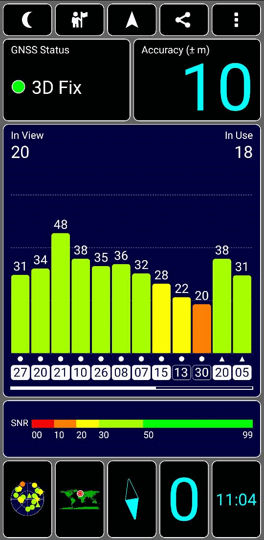
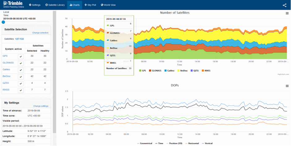
How many GNSS satellites can be received and which are visible in the sky can be determined by an Android app called GPS-Test. GPS-Test shows us which GNSS satellites the phone is currently receiving and Sat-AR shows us which satellites are where in the sky. The screenshot of GPS-Test shows us 12 satellites in the display window and the scroll bar shows us that more than 12 are being received. GPS-Test shows not only the GPS satellites, but also the Glonass satellites. In the upper left corner of the display window we can see that 20 satellites are visible. On the right we can see that 18 satellites are in use. Below left one sees in which angle the satellites are in the sky. With the Trimble GNSS Planning web page we can see the number of satellites spread over the day. The chart below shows the number of satellites for Neustadt am Rübenberge near Hannover. In the worst case only 6 American GPS satellites are visible but 10 Chinese Beidou satellites. Besides there are 7 Russian GLONASS satellites and 6 European Galileo satellites.
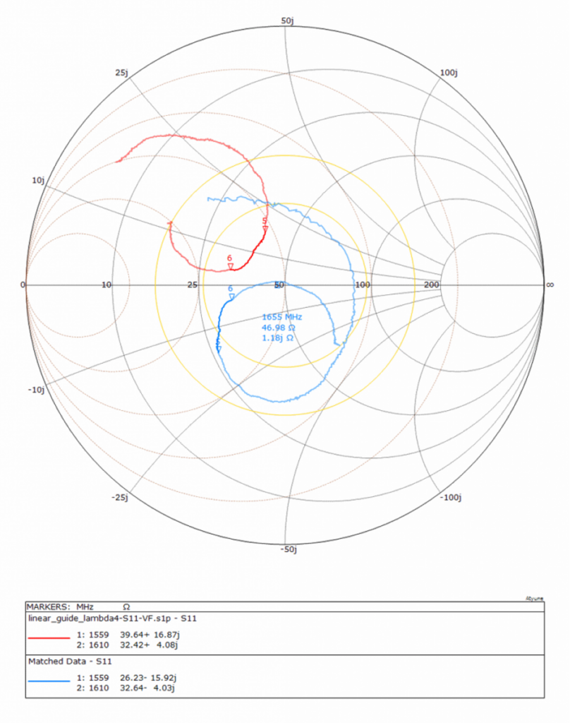
GPS DIY antenna: Smith chart and return loss
The red curves show the antenna not matched to 50 Ohm in the return loss diagram and in the Smith chart. The blue curve shows the attempt to simulate matching. The return loss in the blue curve is better than -35 dB. However, the antenna cannot be adjusted to 50 Ohm and simultaneously pulled to 1575 MHz medium frequency. The 50 ohms are almost reached at 1655 MHz. The frequency is too high and the nail should be a bit longer. The red curve is perfect for this, which was adjusted without VNA. But it also shows that only shortening the antenna without VNA will not achieve the optimum. The blue curve would shift towards the red curve with a slightly longer antenna.
Anyone who has problems with their antenna or radio can contact us. It does not have to be a nail antenna or a 4 cent antenna. We take care of the design of almost any antenna from 400 MHz to 6000 MHz.
The post GNSS Antennas and Recycling appeared first on akorIoT.
]]>The post Certifying your IoT device appeared first on akorIoT.
]]>
The CE Radio Equipment Directive 2014/53/EU (RED) certification only applies to the radio module and is not transferred to the complete circuit board with the enclosure. You will have to test again, but only a subset of the tests already passed by the GSM module.
Re-testing is necessary because a badly designed antenna with a poor return loss will generate a lot of harmonics, it may not transmit in the correct frequency band will have high energy consumption and in extreme cases the harmonics can damage the radio module. Harmonics can also be generated even when using a high-quality chip antenna if it is poorly placed on the PCB, with too small a ground plane or with bad platinum layout (DP question I don’t understand this). If you don’t have any design experience or measurement equipment (such as a MegiQ Vector Network Analyser), it is difficult to evaluate the performance of an in-house designed PCB antenna and either redesign it or correct the impedance with a matching circuit.
If you lack the necessary experience, don’t worry! Even experienced radio designers can struggle with the requirements of IoT radio design. To be on the safe side, we recommend a modest investment in the time of an experienced external consultant from the arkorIoT team for at the start of your antenna journey. A consultation with report often costs only 3 to 4 hours working time and saves thousands of Euros in radio certification mishaps.
Below is a summary of the arkorIoT team’s available wireless IoT related services:
- Impedance matching of the antenna in the device (chip, PCB antenna, helical antenna)
- Guidance on antenna design if undertaken by the client
- Antenna layout of the dual F-antenna on an empty PCB in the customer’s enclosure
- Antenna layout of any other custom PCB antenna type: helix antenna, Flex PCB antenna, antenna punched from tinplate, antenna printed on plastic in housing, antenna on ceramic, slot antennas and many more techniques
- Antenna with radio module and power supply for extremely low power consumption
- Assisting in the implementation of the antenna or power supply concept on the fully-featured PCB of the customer
- Development of the whole PCB including an antenna with software development by the customer
- Development of the whole device (HW + SW) following the client’s specifications
- Licenses to reference designs for NB-IoT, LTE-M, GSM, GNSS, BLE, Wi-Fi, MCU, sensors and charging electronics. Over 20 application examples are provided with an open block diagram and the possibility for customers to develop their own code using a free C compiler
- Preliminary measurements and tests required for radio certification
- Radio certification according to RED (CE), FCC and several more standards
- Workshops at the client’s office or via video conference
- Training and seminars on radio technology and radio certification
The post Certifying your IoT device appeared first on akorIoT.
]]>The post Request for an NB-IoT antenna appeared first on akorIoT.
]]>
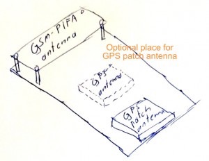
Another request for a custom PCB antenna for NB-IoT. Since we invested in NB-IoT early on, we can bring a lot of experience. Simply taking over a layout of an antenna for an unlicensed band like LoRaWAN (868 / 915 MHz) usually does not work. It may be sufficient for first tests but if the antenna bandwidth of the NB-IoT antenna does not fit, this usually leads to harmonics and a negative result for the radio certification.
Request for NB-IoT antenna via LinkedIn:
Hi Harald, Thanks for the industry knowledge you share on here. Lots of useful information. We’re in the process of deploying our NB-IoT solution in the UK but are waiting for coverage to catch up. I have already designed a PCB, with an OTS antenna and integrated PCB antenna (similar to TI’s helical design) I must consult with you before our next PCB redesign as we’re looking to reduce the overall cost of the system. Regards
Answer to the NB-IoT customer:
Thanks for the kind words.
My recommendation is always to first build a prototype with an empty PCB in the original case. If you don’t have the empty case yet, you can cut it out of plastic plates of the same material and glue it together. 3D Printing is only possible to a limited extent because not all plastics can be printed. If you print ABS, you have to print it fully (no combs in print) because the epsilon R of the plastic and the thickness of the plastic influences the antenna. For more information see the IoT/M2M Cookbook.
Since we work with various manufacturers of external antennas we can also offer you the manufacture of the injection tool up to the production of the whole device. If your device is mounted on a street lamp, then you need a UV-resistant plastic. Antennas for roof mounting on cars are UV-resistant. We are thus well prepared for the practical use of your design.
The PCB antenna from TI will probably not provide the necessary frequency bandwidth for band 8 and band 20 in the EU. In the USA the lowest frequency goes down to 620 MHz. In Australia up to approx. 690 MHz. We can cover more about this in a Kick-Off meeting via Skype with a presentation of a few slides.
The typical engagement with the arkorIoT team is as follows:
- Purchase of the IoT M2M Cookbook, read the book and learn the basics.
- Telco/Skype to kick off the project (approx. 4 hours working time with preparation and follow-up)
- Prepare an empty board with an antenna in the original case. Often also with the radio module and USB cable for live testing.
- Measurement of the Radiation Pattern in 3 axes (recommended option)
- Delivery of the documentation incl. Gerber Files
- “Copy” of our design by your team with all components
- Design review by our akorIoT team or accompaniment of the development by phone, Skype or e-mail
- Production of prototypes and matching of the antenna by our team
- Mostly then up to 10 further versions up to the serial board required
- Measurement of the serial PCB and re-matching of the antenna
- Pre-tests for radio certification in our laboratory and in the test laboratory
- Possible adjustment of the matching network and Worst-Case modification of the PCB (very rare)
- Radio certification of the device and accompaniment by the akorIoT team. We are always in the room during the measurements and check whether the measurements are correct in the test laboratory. Measurement errors lead to a negative test report.
If required, we can develop the series PCB on the basis of the customer’s prototype (pre-production) and take care of the radio certification. The software development is then still with the customer. If required, we put together the “all-round carefree package” and develop the hardware plus firmware, plus software on the server and app on the smartphone.
Since we have extensive experience with NB-IoT projects and development of antennas, we would like to guide and support your project and we are happy to make you a commercial offer. We need a sketch or drawing of the case with dimensions to be able to estimate the size of the board. If the board is too small compared to the wavelength of the lowest frequency, the development costs will increase. In the worst case, no antenna can support the application in this format.
Extract of wireless IoT related services:
- Matching of the antenna in the device (chip, PCB antenna, helical antenna)
Guidance on antenna design if undertaken by the client - Antenna layout of the dual F-antenna on an empty PCB in the customer’s enclosure
- Antenna layout of any other custom PCB antenna: Helix antenna, Flex PCB antenna, Antenna punched from tinplate, Antenna printed on plastic in housing, Antenna on ceramic, Slot antennas and many more techniques
- Antenna with radio module and power supply for extremely low power consumption
- Assisting in the implementation of the antenna or power supply concept in the fully-featured PCB of the customer
- Development of the whole PCB including an antenna with software Development by the customer
- Development of the whole device (HW + SW) following the client’s specifications
- Reference designs with NB-IoT, LTE-M, GSM, GNSS, BLE, Wi-Fi, MCU, sensors, charging electronics for over 20 applications with an open block diagram and the possibility for customers to develop their own code using a free C compiler
- Preliminary measurements and tests required for radio certification
- Radio certification according to RED (CE), FCC and several more standards
- Workshops at the client’s office or via video conference
- Training and seminars on radio technology and radio certification
We look forward to receiving your inquiry. In most cases the IoT M2M Cookbook or the reference design akorIoT SensPRO is only the beginning. After that there are often follow-up orders for the services mentioned above. “akor” is the ancient Celtic word for “open” and we prefer openness in our concepts, and like to share our knowledge in training and to maintain open communication with our customers.
The post Request for an NB-IoT antenna appeared first on akorIoT.
]]>